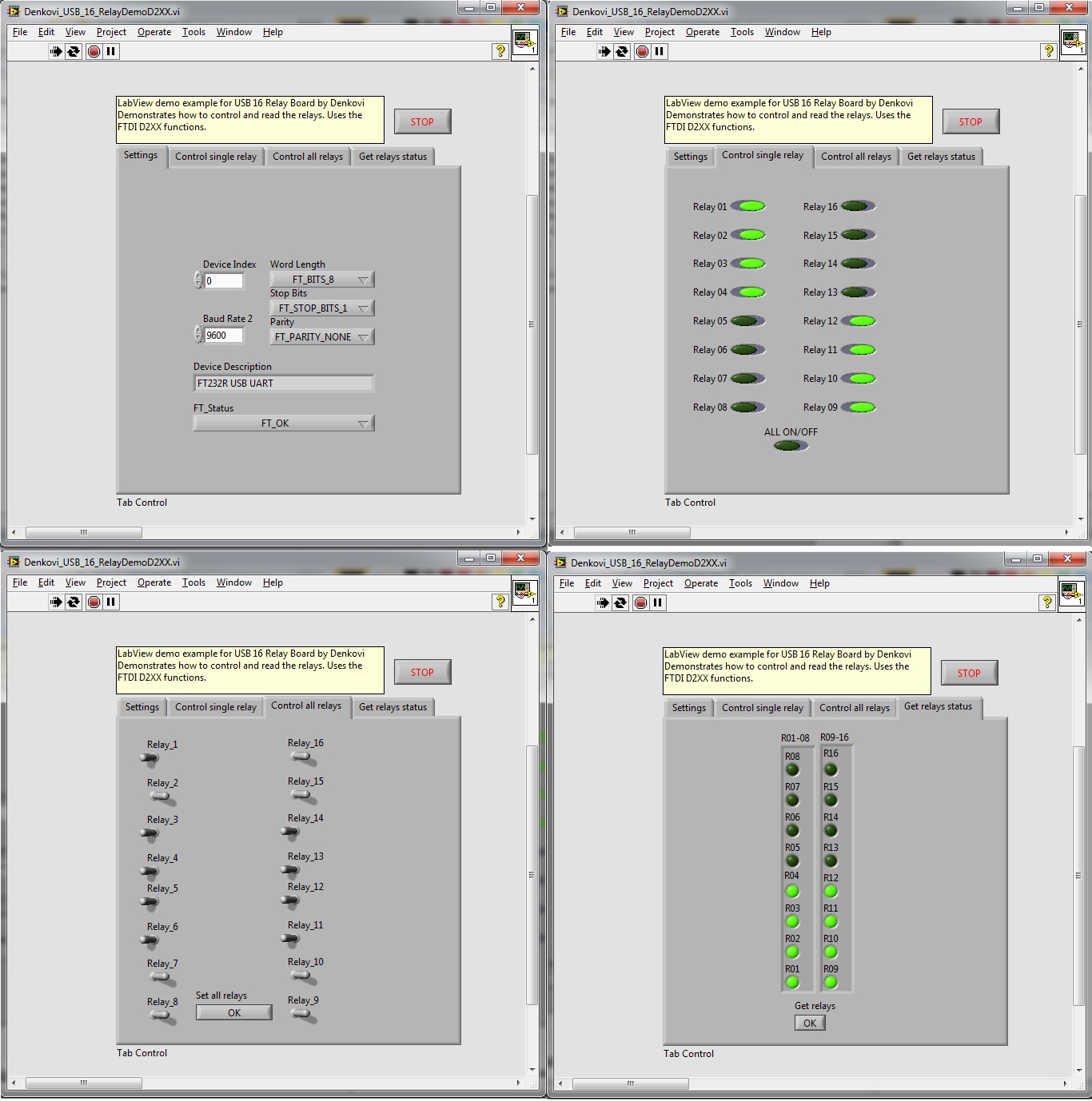
Serial Communication Labview Example


Your instrument should have specific commands for collecting and transmitting data, and sending those commands to the instrument from the VISA Test Panel will confirm that you have a connection. NI-VISA makes serial instrument programming fast and easy. This example opens a VISA session to a serial device.
2017 / May 2017; 7 months ago ( 2017-05):,,,,, analysis and,, design Website Laboratory Virtual Instrument Engineering Workbench ( LabVIEW): 3 is a system-design platform and development environment for a from. The graphical language is named 'G'; not to be confused with. Originally released for the Apple in 1986, LabVIEW is commonly used for,, and industrial on a variety of (OSs), including, various versions of,, and.
The latest versions of LabVIEW are LabVIEW 2017 and LabVIEW NXG 1. Willy Wonka Ost Rapidshare Search. 0, released in May 2017. Contents • • • • • • • • • • • • • • • • • • • • • • • • Dataflow programming [ ] The programming paradigm used in LabVIEW, sometimes called G, is based on data availability. Fantasma Cornelius Zip Nc. If there is enough data available to a subVI or function that subVI or function will execute.
Execution flow is determined by the structure of a graphical block diagram (the LabVIEW-source code) on which the programmer connects different function-nodes by drawing wires. These wires propagate variables and any node can execute as soon as all its input data become available. Since this might be the case for multiple nodes simultaneously, LabVIEW can execute inherently in parallel.: 1–2 and hardware is exploited automatically by the built-in scheduler, which multiple OS threads over the nodes ready for execution. Graphical programming [ ] LabVIEW integrates the creation of user interfaces (termed front panels) into the development cycle. LabVIEW programs-subroutines are termed virtual instruments (VIs). Each VI has three components: a block diagram, a front panel, and a connector panel. The last is used to represent the VI in the block diagrams of other, calling VIs.